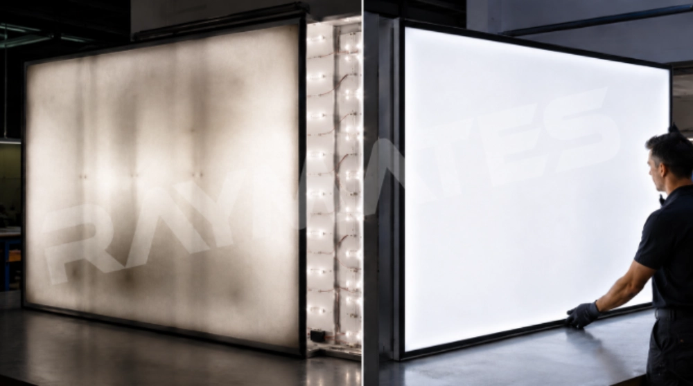
Dark bands, dim corners, and visible seams in Large Backlit Panels usually come from several factors working together. The LED layout may leave gaps between light fields, a distant section may receive less power, or the diffuser may reveal differences that would otherwise remain hidden. Adding more LEDs without checking the cause can simply replace a dark area with a bright hotspot.
For commercial lightboxes, stone counters, signage, retail displays, and architectural surfaces, the goal is uniform illumination across the entire visible face. Raymates manufactures LED lighting products for these types of applications, including LED sheet lights for backlighting and project-specific lighting solutions. Its engineering approach is useful where standard rectangular lighting layouts cannot easily follow corners, curves, shallow cavities, or irregular panel dimensions.
Why Do Large Backlit Panels Develop Dark Areas?
A dark patch is not always caused by a failed LED. In large illuminated surfaces, the visible symptom can begin with optics, wiring, mounting, or the front material itself. Diagnosis should start with the pattern of the dark area.
Excessive LED Spacing and Incomplete Light Overlap
Each LED creates a light field. Adjacent light fields need enough overlap before they reach the diffuser or translucent surface. If the spacing is too wide for the available cavity depth, darker zones can appear between the LEDs.
Bendable LED Sheet platforms can use tightly controlled LED arrays, with approximately 20 mm spacing serving as a practical reference for reducing visible gaps between neighboring light fields. The actual result still depends on lens angle, cavity depth, diffuser performance, and front-material transmission.
This is why LED spacing for lightbox design should never be selected from pitch alone. A shallow cabinet may need wider beam distribution or closer spacing than a deeper structure using the same front material.
Uneven Power Delivery and Local Brightness Loss
A layout can look correct on the drawing and still develop uneven backlighting after installation. Long cable paths, overloaded connections, poor joints, or unsuitable power distribution can make one section visibly dimmer than another.
For large backlit panels, power injection for LED lighting should be planned from the actual connected load, voltage, cable route, and conductor resistance. There is no reliable universal injection distance for every installation.
Dividing a large panel into controlled electrical zones also makes later troubleshooting easier. If one zone becomes dim, the installer can check that circuit without opening the complete panel.
Diffusion, Edge Conditions, and Backlit Material Differences
A diffuser does more than hide LEDs. It mixes neighboring light fields before they reach the viewer. If it is too thin, too close to the LEDs, or poorly matched to the source, LED points and dark seams become easier to see.
Stone creates another variable. Marble and onyx can have natural differences in thickness, veining, and transmission, so a visually darker area is not always an electrical problem.
For a closer look at diffuser selection and light mixing, see How to Diffuse an LED Panel for Soft, Even Lighting.
How Should Large Backlit Panels Be Designed to Prevent Dark Areas?
Correcting a finished installation costs more than correcting a mock-up. Before production, designers should test the interaction between LED density, beam spread, cavity depth, electrical layout, and the actual front material.
LED Density and Optical Coverage Should Be Planned Together
Start with the viewing surface, not the LED count. LED pitch, lens angle, panel depth, diffuser transmission, and material opacity all affect uniform LED backlighting. A High Density LED Sheet can be useful when a shallow cavity makes visible gaps difficult to control.
Raymates Lensed LED Sheet uses secondary lenses that can provide different light-emitting angles, including 122°, 150°, and 180° options. Wider distribution directs more light laterally between neighboring LEDs, which can help light fields overlap in shallow backlit structures.
For compact cabinets, approximately 20 mm LED spacing can serve as a starting reference, but the final layout should be tested behind the actual acrylic, graphic panel, marble, or other material. A physical sample is more reliable than applying one depth-to-pitch rule to every project.
Power Zones Should Be Calculated Before the Panel Is Built
Large illuminated surfaces should not automatically be treated as one electrical load. Breaking the layout into manageable sections makes power delivery easier to control.
Before installation, calculate the load for each zone, confirm driver capacity, review connector loading, and map the cable path. Power injection for LED lighting should be added where the real electrical design requires it, not at an arbitrary distance copied from another project.
This step is especially important where several LED sheets are joined across a wide surface.
Sheet Layout Should Match the Final Shape and Surface
Corners, narrow returns, curves, and cut-outs are common sources of shadow because standard lighting modules may stop short of the actual illuminated edge. A Custom LED Sheet can be arranged around these difficult perimeter areas without leaving oversized gaps.
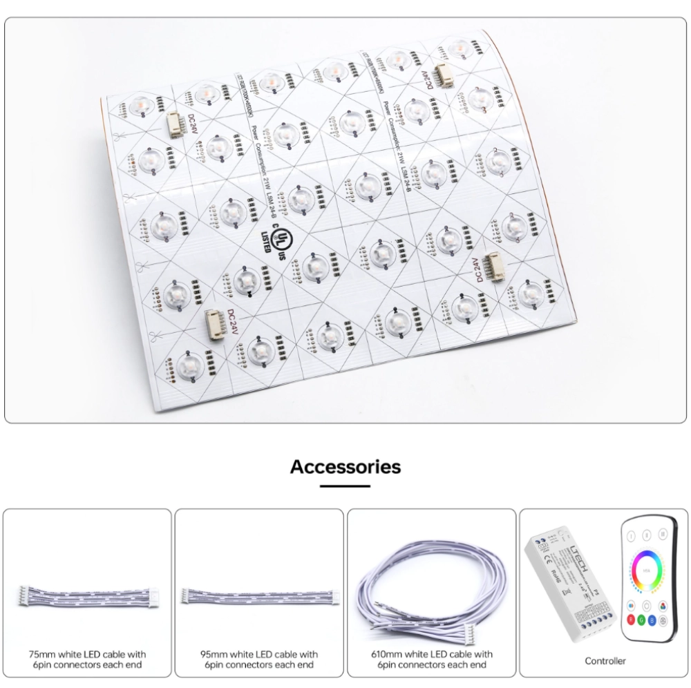
Precision Flexible LED Sheet designs can provide modular one-light, three-light, or six-light cutting sections. Installers can trim the lighting layout around complex perimeter shapes instead of leaving oversized gaps between the light source and the edge.
Where standard dimensions do not fit, Raymates also provides customized lighting solutions covering project-specific requirements such as color temperature, length, voltage, and power. This can be useful when LED spacing for lightbox construction has to follow unusual geometry.
How Can Installation and Commissioning Remove Remaining Dark Spots?
Even a good design can be weakened by poor mounting. Sheet position, cable routing, cutting, connectors, and panel closure all need to be checked before the surface becomes difficult to access.
Dry-Fit Testing Reveals Problems Before Final Assembly
Install the lighting temporarily, power every zone, and place the real front material in position before permanent closure.
View the panel from its normal viewing distance. Check the center, edges, module seams, and areas around power feeds. This dry-fit stage often exposes uneven backlighting that is almost impossible to see when looking directly at bare LEDs.
For large lightbox lighting, photographs taken with the same exposure can also make before-and-after changes easier to compare.
Clean Cutting, Connections, and Mounting Protect Uniformity
LED Sheet should only be cut at the intended positions. Inaccurate cutting can damage terminals or interrupt circuits.
Ultra-thin flexible substrates also need careful handling. Folding, crushing, or allowing a sheet to rebound away from the mounting surface can change its distance from the diffuser and create a local brightness difference.
Stored material should be checked before installation as well. Humidity can contribute to oxidation around soldered connections, creating intermittent electrical faults that may first appear as dim sections.
Troubleshooting Should Be Done Zone by Zone
Start with the simplest checks.
Confirm that every LED section is working. Compare adjacent electrical zones. Inspect the gaps between sheets. Then check the diffuser, mounting depth, and transmitting material.
This order matters. Adding LEDs will not fix a weak connection, and changing the power supply will not fix a physical gap at a panel edge. Systematic testing keeps uniform LED backlighting problems from turning into unnecessary replacement work.
What Can a Large Lightbox Retrofit Teach Us About Dark Areas?
A retrofit should begin by identifying where the dark areas follow the structure. A documented Raymates marble bar-counter project provides a useful example of the same geometry problem that often appears in large lightbox lighting: the light source must follow the illuminated surface closely around difficult corners.
Before the Retrofit: Mapping the Dark Areas
For a lightbox retrofit, first map the dark pattern before removing components. Check whether it follows module seams, edges, cable routes, structural supports, or changes in the front material.
The Raymates bar-counter project involved marble with intricate corners. A fixed rectangular lighting arrangement would have been difficult to position closely around those returns, creating a clear risk of poorly illuminated areas near the perimeter.
The Fix: Reworking Light Distribution and Power Layout
The project used Flex warm white LED sheet beneath the marble. Its one-light-one-cut structure allowed the lighting to be trimmed and arranged around the detailed corners.
The same approach applies when correcting large backlit panels. Reduce oversized gaps first, then check electrical zoning and the distance between the LED surface and the diffuser. If the illuminated geometry changes direction, the lighting layout should follow it rather than stopping several centimeters away.
This is one reason LED Sheet for backlighting works well in irregular stone, display, and signage projects.
After the Retrofit: Verifying Uniformity
After changes are made, reinstall the front material temporarily and inspect the complete surface from the intended viewing position.
In the completed Raymates bar-counter project, the warm white Flex LED Sheet was installed beneath the marble and cut around the intricate corners. The lighting followed areas where a fixed rectangular arrangement would have been difficult to fit, creating the warm backlit effect required for the bar. The client was satisfied with the finished installation.
For a large lightbox retrofit, the same verification process should include seams, edges, center sections, and power-feed areas before final closure.
What Should Buyers Confirm Before Ordering LED Sheets for Large Backlit Projects?
Procurement decisions directly affect installation results. The supplier needs more than panel length and width to recommend the right configuration for large backlit panels.
Match the LED Sheet Specification to the Project
Buyers should confirm the illuminated dimensions, cavity depth, front material, required color temperature, voltage, power arrangement, cutting requirements, and environmental conditions.
An ultra-thin LED backlight sheet can be produced in the 1–3 mm thickness range. Commercial configurations can also use approximately 20 mm LED spacing and CRI ≥90. These formats suit applications such as advertising lightboxes, marble countertops, retail displays, and other projects where mounting space is restricted.
Treat these figures as specification references rather than universal design rules. The final appearance still needs to be checked with the real installation material.
Custom Drawings and Sample Validation Reduce Project Risk
For custom projects, send the supplier panel drawings, installation depth, front-material details, electrical requirements, and expected lighting effect before bulk production.
Raymates can work from project requirements and prepare customized solutions, project drawings, and installation drawings. A sample section is particularly useful for large lightbox lighting, because it can reveal optical gaps and electrical issues before the complete structure is built.
Service and Contact Support the Final Specification
If a project has repeated dark seams, unusually shallow depth, difficult corners, or uncertain power zoning, prepare the panel dimensions, material details, wiring layout, and installation drawings before discussing the specification. You can contact Raymates with this information so the LED Sheet layout and customization requirements can be reviewed against the actual structure.
Conclusion
Dark areas in Large Backlit Panels rarely come from one isolated problem. LED spacing, lens angle, diffusion, panel depth, front-material transmission, electrical distribution, and mounting position all affect what the viewer finally sees.
For Large Backlit Panels, the safer process is to diagnose the dark pattern first, test a representative section, divide the electrical load into manageable zones, and check the complete surface before permanent closure. Where shallow depth or complex geometry makes conventional layouts difficult, a cuttable LED Sheet can make light-source positioning easier to control.
FAQ
How Can I Make Large Backlit Panels Look More Uniform?
Start by checking LED spacing, cavity depth, diffuser performance, module seams, and power delivery. If dark areas follow sheet gaps, adjust the optical layout. If they follow long wiring routes or particular electrical zones, inspect power distribution. Always test the system behind the actual front material.
What LED Spacing Works for a Backlit Lightbox?
There is no single spacing that works for every lightbox. Approximately 20 mm spacing can be used as a practical reference for some LED Sheet layouts, but lens angle, cavity depth, diffuser properties, and front-material transmission also matter. A sample section should be tested before final production.
Is LED Sheet Better Than LED Strip for Large Backlit Panels?
It depends on the panel structure. LED Sheet is useful for wide surface coverage, shallow installations, cut-to-fit layouts, and irregular shapes. LED strip remains practical where linear routing and sufficient cavity depth are available. For Large Backlit Panels with corners, curves, or restricted mounting depth, LED Sheet can make light distribution easier to arrange consistently.